
Build Electrics & heating New
Rev counter retrofit – new life for an old tachometer
A broken diesel rev counter from the used market, a modern instrument cluster board instead of the old flexible circuit, new electronics from pcbT3machin and a 3D-printed needle adapter – and in the end the fuel and temperature gauges read correctly again.
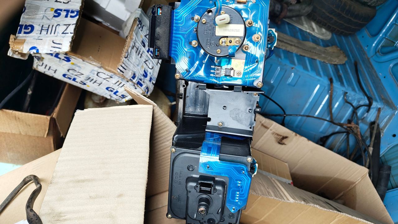
My T3 never had a rev counter. So I bought a used, broken diesel rev counter together with the speedometer unit and set about repairing it. It took a few stages to get everything working – and a bit of help from the T3 community.
What I fitted
- Used speedometer unit with diesel rev counter
- T3 instrument board from fiz-o-matic instead of the original flexible circuit
- New circuit board in the rev counter from pcbT3machin
- 3D-printed adapter for the rev counter needle
- Signal wire from terminal W on the alternator
How this post is structured
The used part
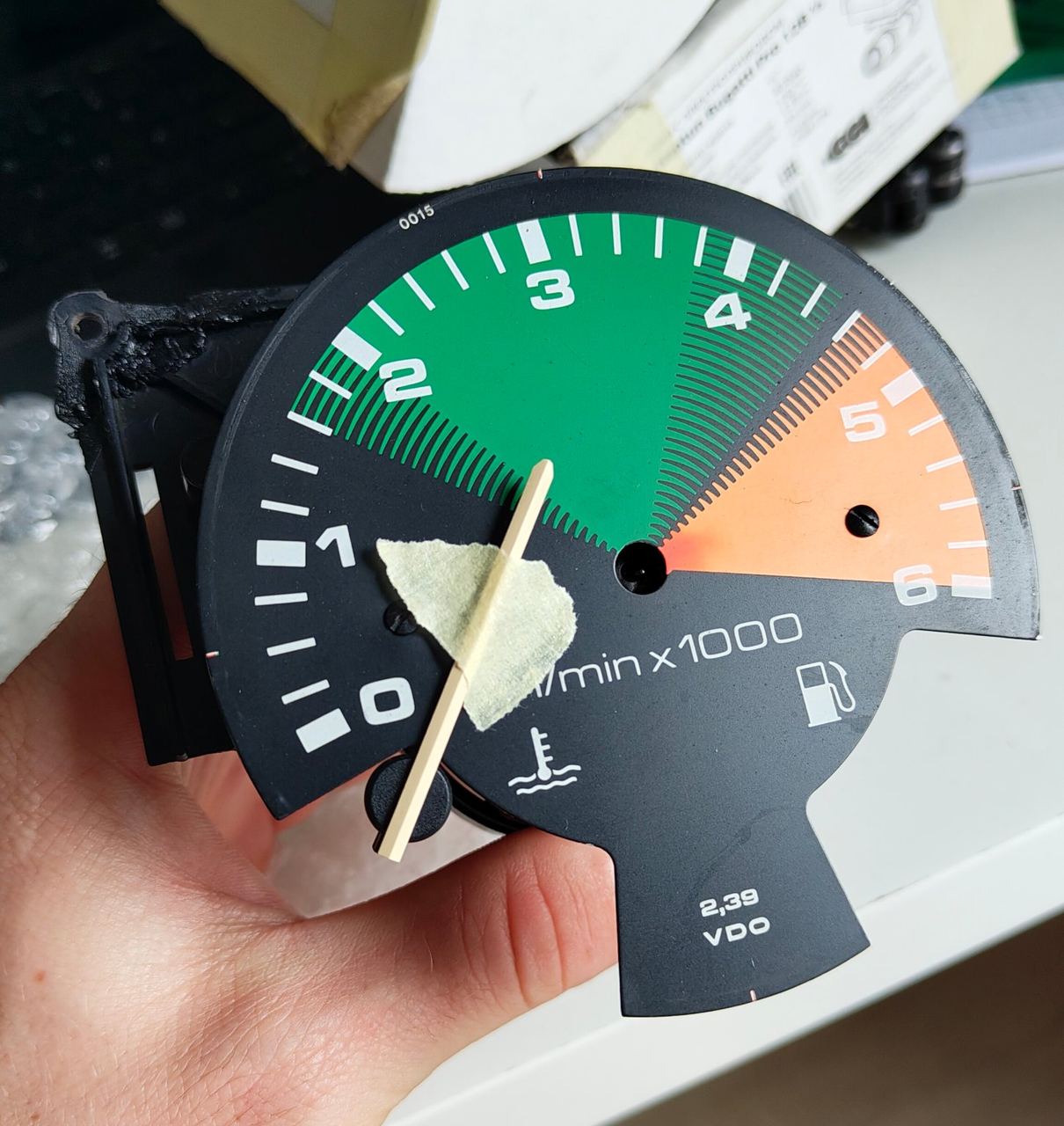
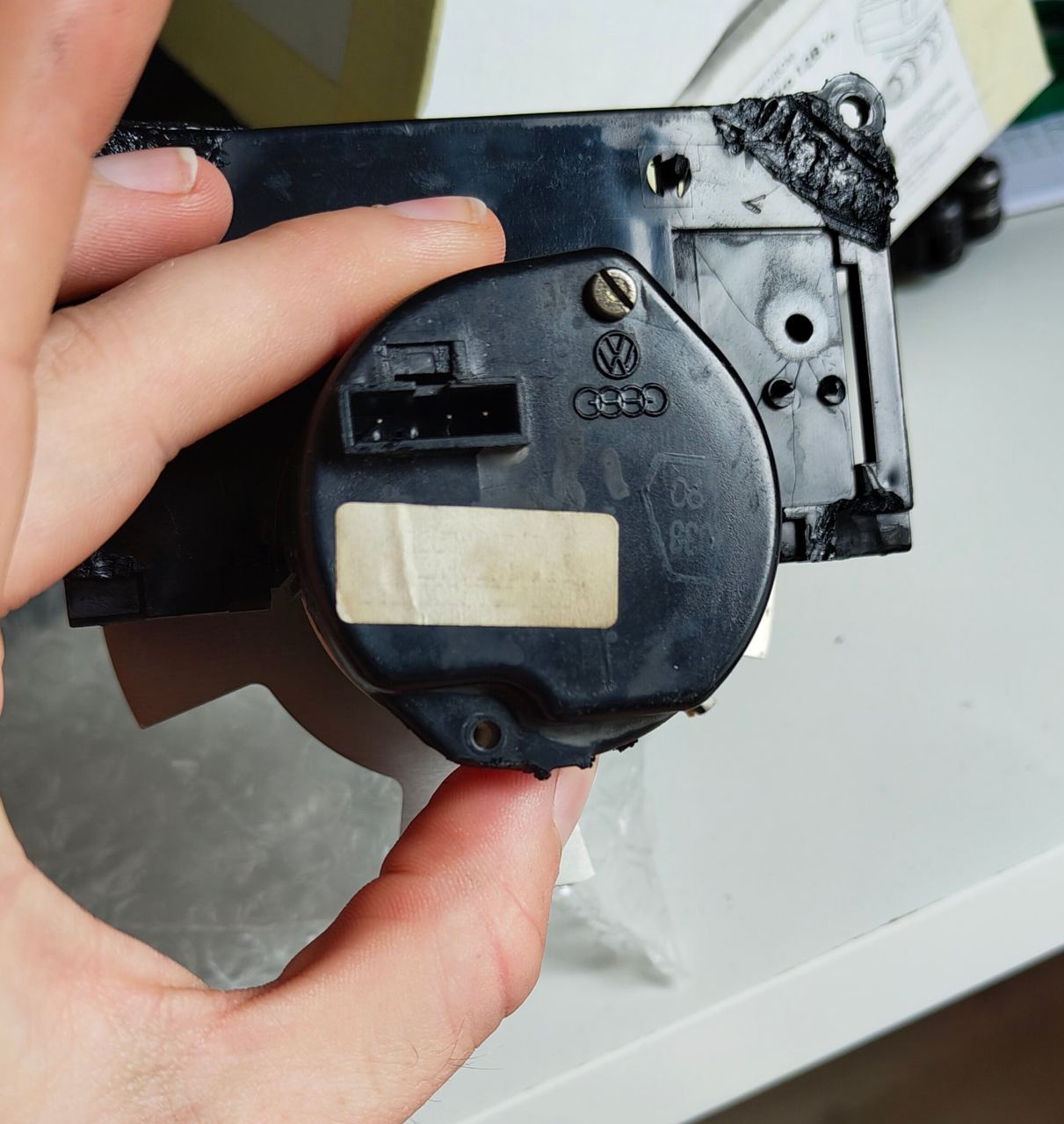
The rev counter had several problems at once:
- The rev counter itself was broken.
- The delicate needle had snapped off.
- The plastic housing was cracked at the corners and had been patched up.
Worth knowing: in the cluster with a rev counter, the fuel gauge and the coolant temperature gauge sit inside the rev counter too. So they also have to work properly in the end.
A new circuit board instead of the flexible circuit
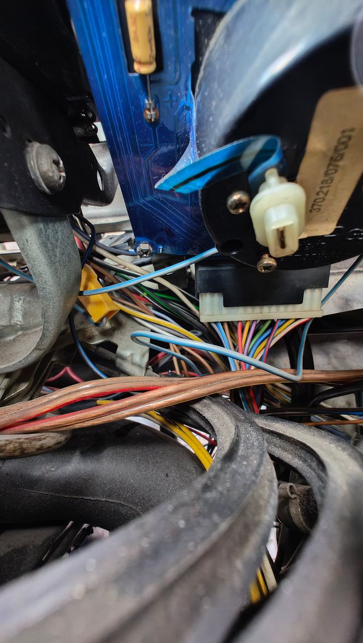
From the factory, the T3 has a flexible printed circuit behind the instruments. It consists of several layers with the conductor tracks between them – and over time these layers separate. Typical symptoms are flickering lights, a wrong fuel reading or a dead temperature gauge.
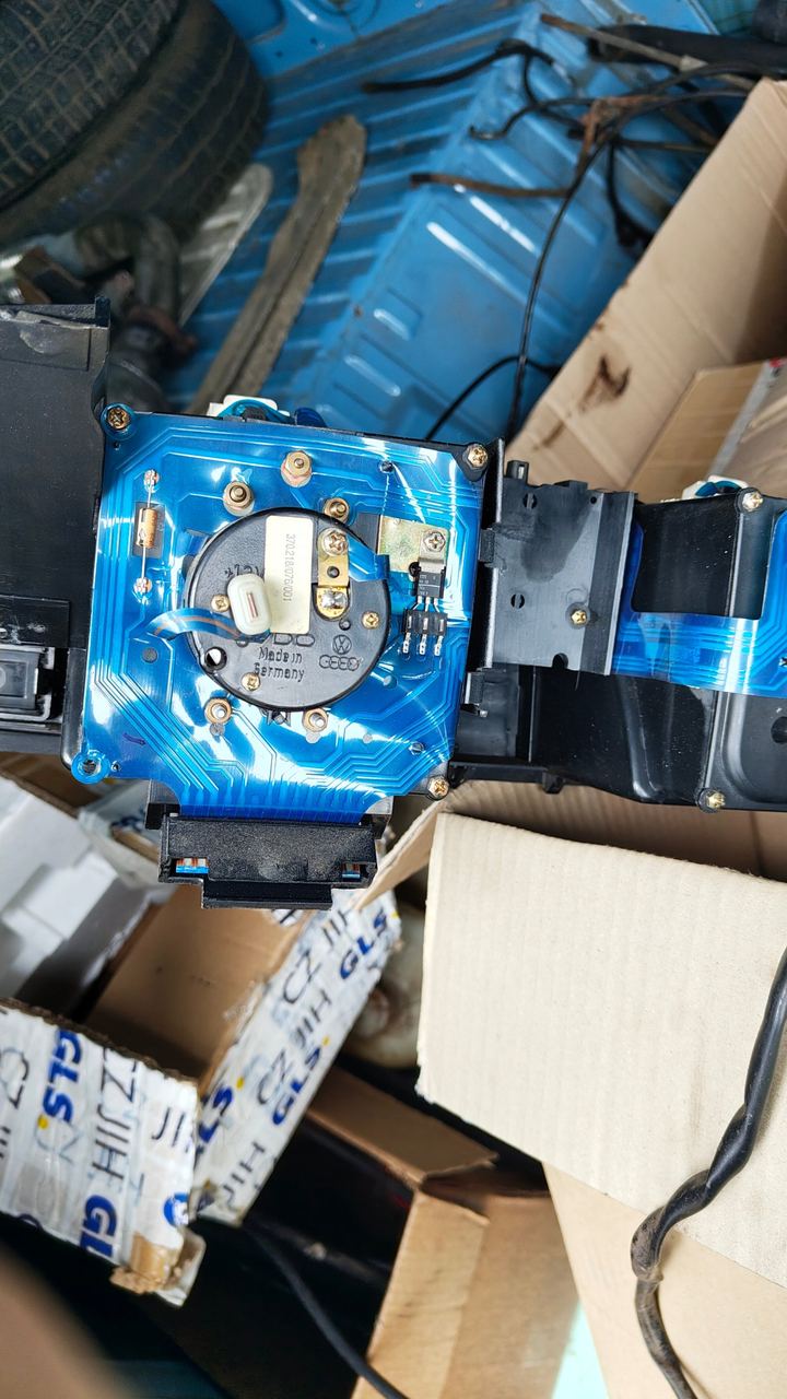
I replaced the flexible circuit with the T3 instrument board from fiz-o-matic – a modern kit I can only recommend:
- It includes everything you need to replace the old flexible circuit.
- You don't need any tools apart from a suitable screwdriver – no soldering iron either.
- For diesels there's a slot for the glow plug warning light, and the LED is included.
- Detailed installation instructions are available online.
Tip: You order by model year, not by year of manufacture.
New electronics for the rev counter
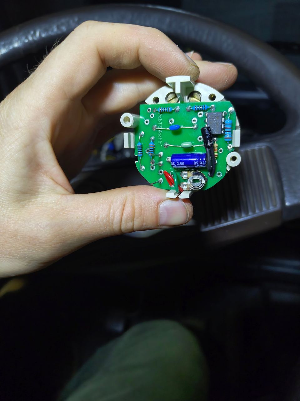
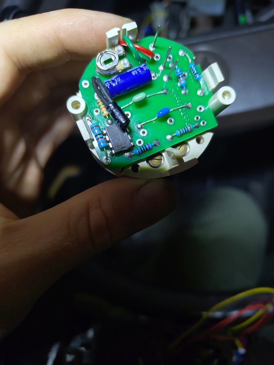
I couldn't repair the rev counter itself. So through a Facebook group I got in touch with the person behind pcbT3machin. He specialises in T3 instruments – repairs, new circuit boards and plastic parts – and had already helped me adapt the fuel gauge mechanically to the Syncro tank (more on that below).
He fitted a new circuit board to my rev counter – at a fair price.
Needle and cover from the 3D printer
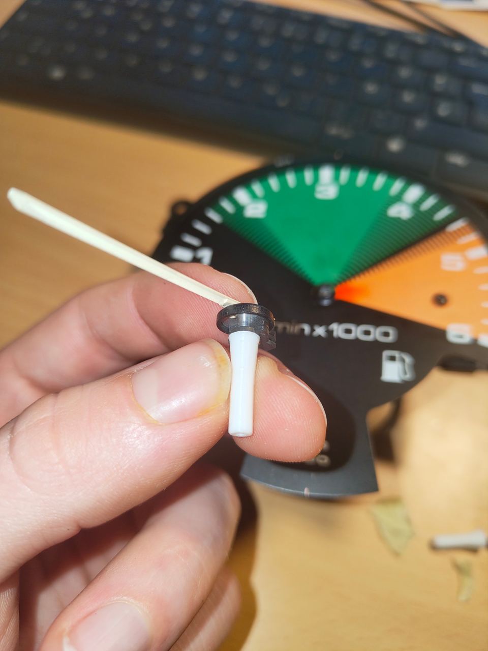
The rev counter needle is pretty fragile, and mine had snapped off. On Thingiverse I found an adapter for the needle and fitted it.
There's also a matching design there for the broken plastic cover of the rev counter.
Calibrating the fuel and temperature gauges
Since the Syncro conversion, my bus has the Syncro's 70-litre tank. pcbT3machin had already explained to me how to adapt the fuel gauge to it mechanically. Because the fuel gauge now sits in the rev counter, I calibrated it to the Syncro tank again – and did the same with the coolant temperature gauge.
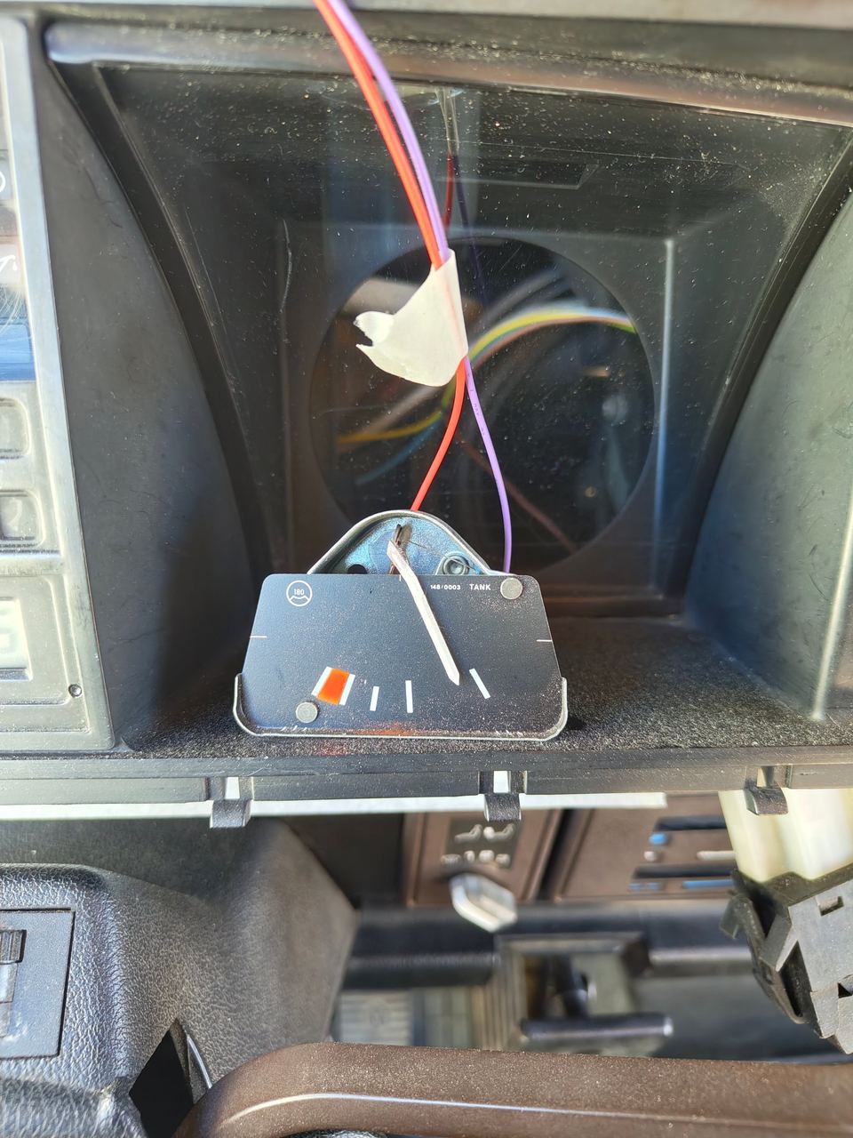
Wiring: terminal W, positive and negative
On a diesel, the engine speed signal doesn't come from the ignition but from terminal W on the alternator. I had already run that wire to the front during the AAZ engine swap. I took positive and negative for the rev counter straight from the fiz-o-matic board.
| Connection | Source |
|---|---|
| Engine speed signal | Terminal W on the alternator, wire run to the front during the AAZ swap |
| Positive | straight from the fiz-o-matic board |
| Negative | straight from the fiz-o-matic board |
Links and sources
- fiz-o-matic: T3 instrument board – replacement for the flexible circuit, with installation instructions
- pcbT3machin – repairs, circuit boards and plastic parts for T3 instruments
- Thingiverse: adapter for the rev counter needle
- Thingiverse: cover for the rev counter
- On this blog: Syncro conversion and AAZ engine swap
Questions about the build? Get in touch – I'm happy to help.